Communicate with Real Actuators
This page guides you through the available communication methods with a real PULSAR actuator.
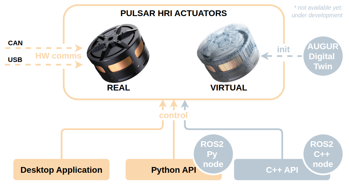
Currently, there are two supported modes of communication:
- USB: Direct connection to a single actuator using a USB-C cable.
- CAN (via USB-to-CAN adapter): Used for connecting one or multiple actuators on a CAN bus.
USB Communication
This is the most straightforward method for connecting a single actuator during development or testing.
Warning
Before continuing, ensure that your actuator is securely mounted and powered on, as explained in the Set Up Real Actuators guide.
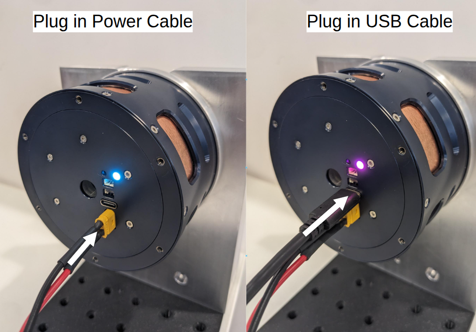
1. Connect USB
Use a USB-A to USB-C cable to connect the actuator directly to your computer.
💡 The actuator will switch LED color when USB is successfully connected.
2. Check USB Communication
To verify the connection either start up the PULSAR Desktop App, or use the Python API CLI tool.
You should see your actuator listed.
CAN Communication
By connecting actuators on the same CAN bus, you can control one or multiple actuators together. Communication is enabled through a CAN adapter device.
The steps below guide you through connecting a single actuator via CAN. The same procedure can then be extended to multiple actuators.
Warning
Before continuing, ensure your actuator is securely mounted and powered on, as explained in the Set Up Real Actuators guide.
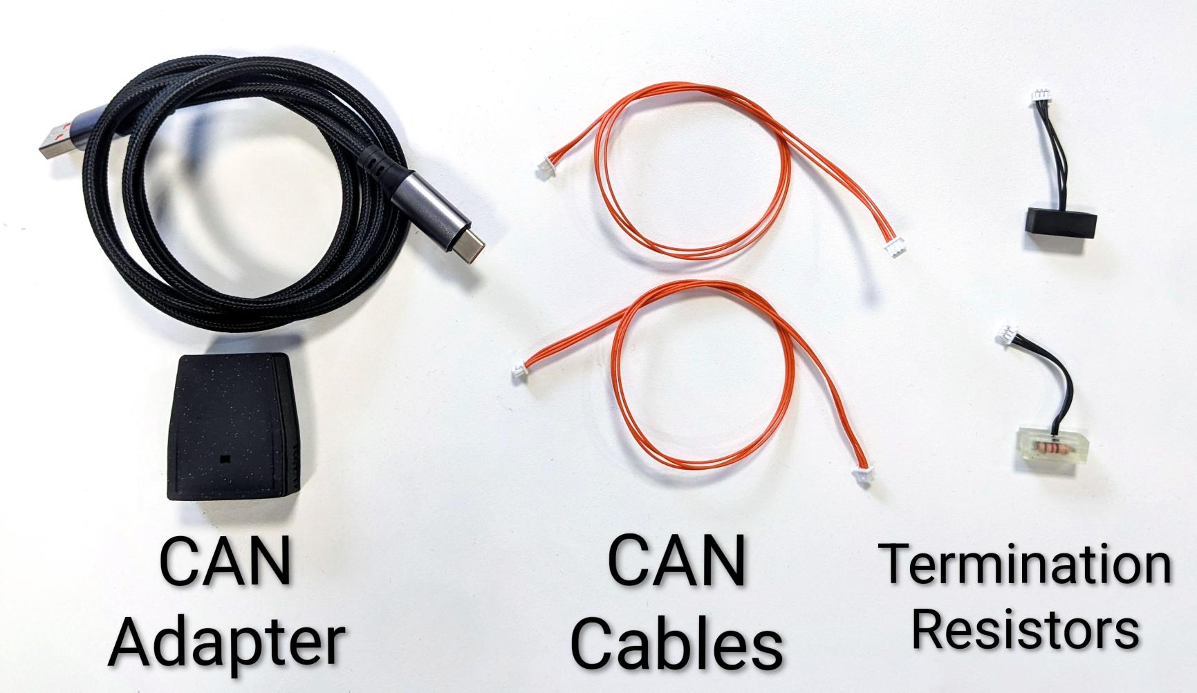
1. Prepare the Hardware
To connect one actuator on a CAN network, you will need:
- 1× CAN adapter – we recommend the PULSAR USB-to-CAN adapter (two CAN ports).
- 1× USB-A to USB-C cable – to connect the adapter to your computer.
- 1× CAN bus cable – 3‑pin Molex PicoBlade cable.
- 2× Termination resistors (TR) – 120 Ω, one at each end of the bus.
Note
CAN ports are bidirectional: there is no distinction between input or output. On both actuators and the CAN adapter, either port can be used.
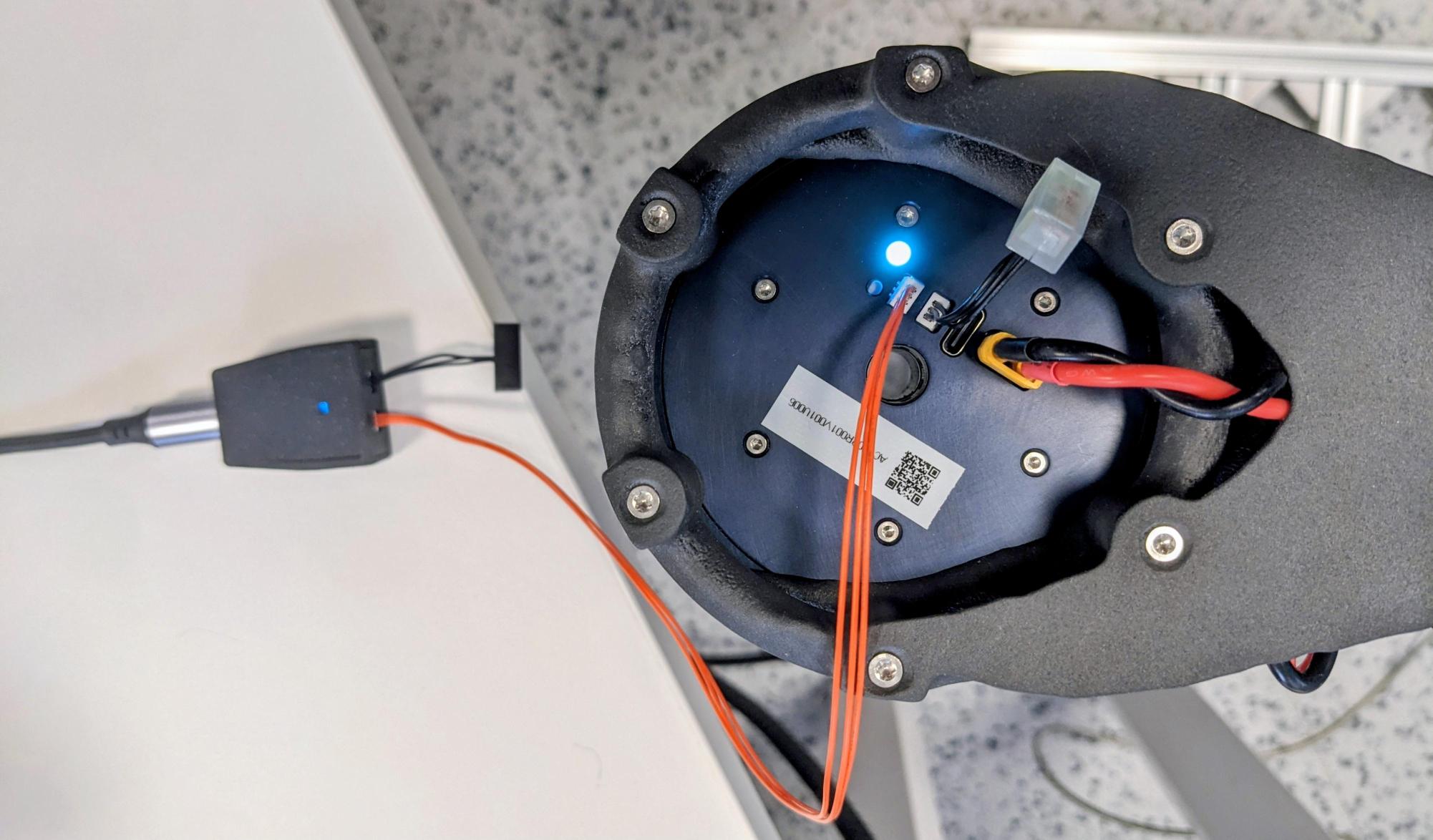
2. Physically Connect the Hardware
- Connect the CAN adapter to your computer using a USB‑A to USB‑C cable. The adapter LED should light up.
- Plug one termination resistor into one CAN port of the adapter.
- Plug a CAN cable into the other CAN port of the adapter.
- Connect the other end of the CAN cable to a CAN port of the actuator.
- Insert the second termination resistor into the remaining CAN port of the actuator.
Your setup should now look like this:
3. Connect via CAN
To communicate via CAN using the Python API or the Desktop App, you will need the CAN address of the actuator.
- Each actuator has a unique integer CAN address stored in its firmware.
- The address is automatically included in CAN messages so that each actuator knows which messages to respond to.
To discover the address, use the Command Line Interface tool that comes with the Python API:
Note
The output of this command lists the actuator addresses detected on the CAN bus.
Example output:
4. Troubleshooting
CAN Adapter Issues
If the CLI output shows:
This means the CAN adapter is not detected.
Check the following:
- Ensure the adapter is plugged in and the LED is on.
- Try unplugging and replugging the USB cable.
- Try a different USB port on your computer.
- Try a different USB cable.
- If the problem persists, contact support.
CAN Bus Issues
If the CLI output shows:
Connecting to CAN adapter on port /dev/ttyACM0 ...
Scanning addresses from 0x10 to 0xFF ... (CTRL+C to cancel)
Found 0 addresses: []
This means the adapter is connected, but no actuator is found.
Check the following:
- Ensure the actuator is powered on.
- Verify all cables and termination resistors are properly connected.
- Try replacing the CAN cable.
- Try replugging the CAN adapter.
- If the problem persists, contact support.
5. Connecting Multiple Actuators
To add more actuators:
- Daisy‑chain additional CAN cables between actuators.
- Place termination resistors only at the two ends of the bus.
Example CLI scan output with two actuators:
Connecting to CAN adapter on port /dev/ttyACM0 ...
Scanning addresses from 0x10 to 0xFF ... (CTRL+C to cancel)
Device found: address 0x1D (29) model PULSE98_V1   firmware version 21
Device found: address 0x25 (37) model PULSE98_V1   firmware version 21
Found 2 addresses: [29, 37]
6. Bus Topologies
The CAN adapter can be placed:
- At the start of the chain – all actuators connected in series (common in robotic arms).
- In the middle of the chain – two actuator chains branching out (common in quadrupeds or humanoids).
Both setups require termination resistors at the two physical ends of the bus.
7. Multiple CAN Buses
It is possible to use multiple CAN adapters on the same computer, each creating an independent CAN bus. This is useful for complex robots.
Example:
- Upper limbs – one CAN adapter in the torso connects to the arm actuators.
- Lower limbs – another CAN adapter in the torso connects to the leg actuators.
This allows parallel, modular control of different parts of the system.
Success
You can now connect to the actuator(s)!! You can now interact with the actuator either using:
Question
Need help or something doesn’t work? Head over to the Support page: we’ve got your back.