Hardware
Electrical interfaces
Power bus
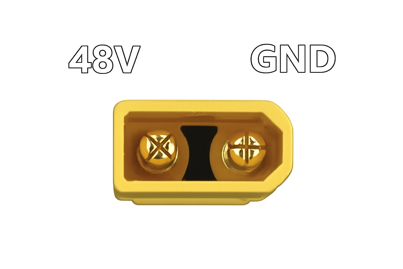
- Voltage: 48 V DC
- Current: up to 30 A
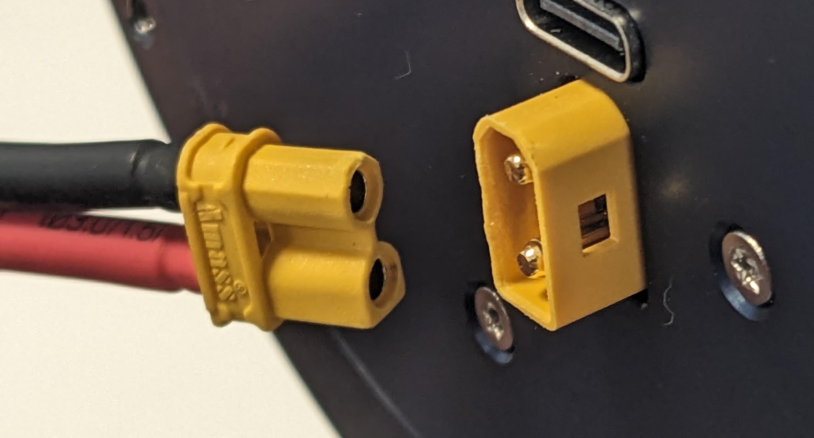
- Actuator connector: XT30 male
Actuators usually draw much less than the maximum current without load, but the supply and wiring must be suitable for the configured limits and application. If the supply cannot provide the possible demand, configure an appropriate current or torque limit.
Power cable
The actuator requires an XT30 female connector on the power cable.
Danger
Verify polarity before applying power. Incorrect wiring can damage equipment and create a fire or injury hazard.
USB
The actuator USB connector supports direct connection to one computer for configuration, single-actuator testing, control, and maintenance. Use a standard USB-A to USB-C cable.
Direct USB uses actuator address 0 in Pulsar Python SDK; see the direct USB guide and Python SDK USB quickstart.
For a shared DC bus or applications that may return energy, review Regenerative energy management.
CAN FD
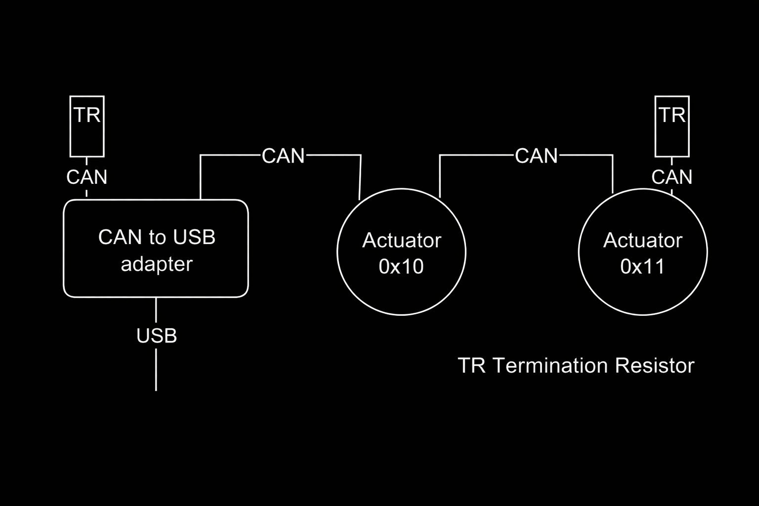
PULSE actuators support CAN FD with a 1 Mbit/s arbitration rate and selectable 1 or 5 Mbit/s data phase. Dual CAN connectors allow daisy chaining.
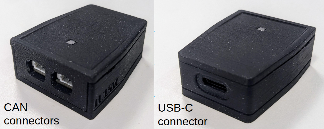
USB-to-CAN adapter
A CAN adapter connects the host computer to the actuator bus. PULSAR HRI provides a USB-to-CAN adapter.
CAN cables
Compatible cables use 3-pin Molex PicoBlade connectors.
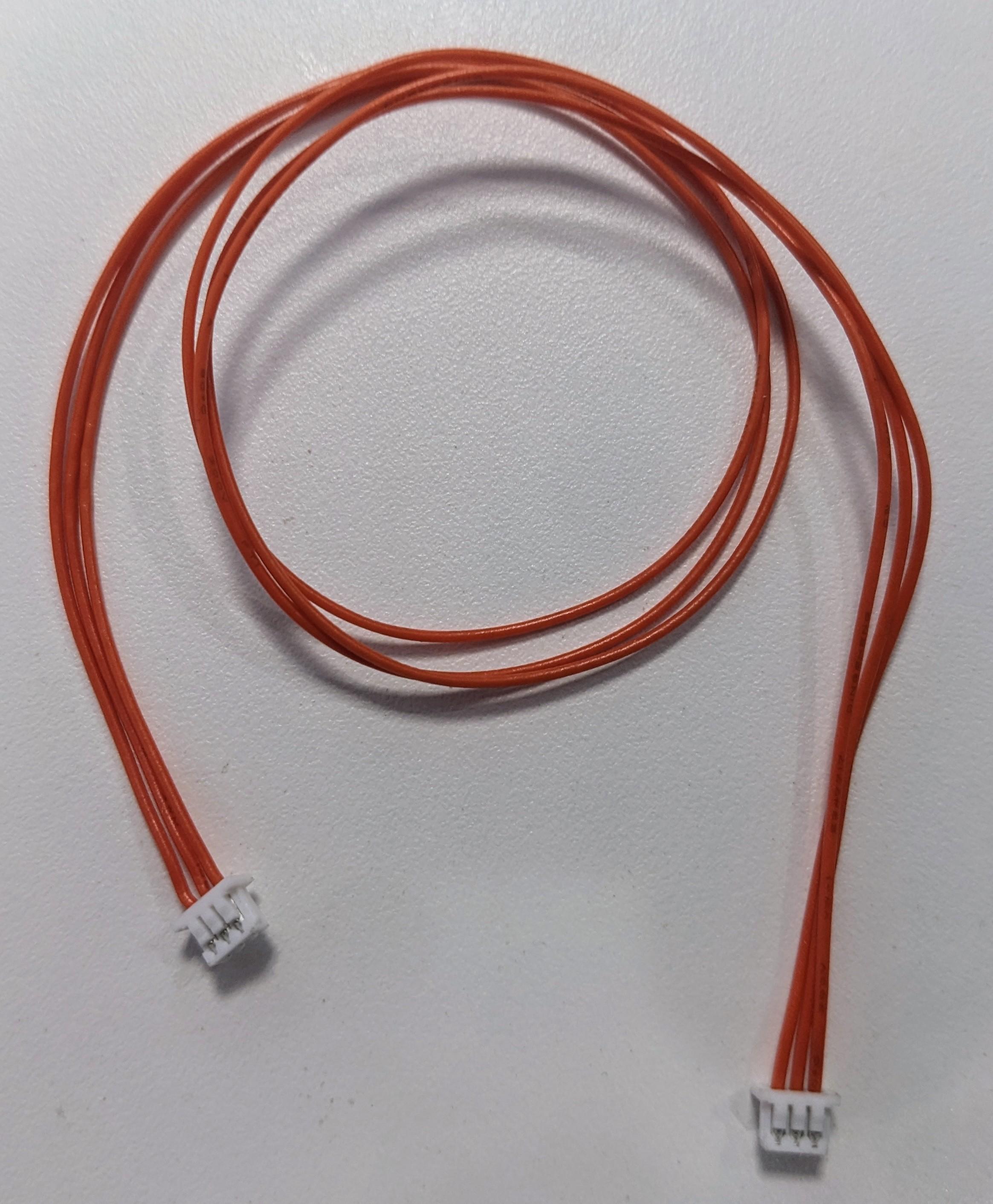
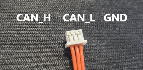
Preserve the pinout at both cable ends:
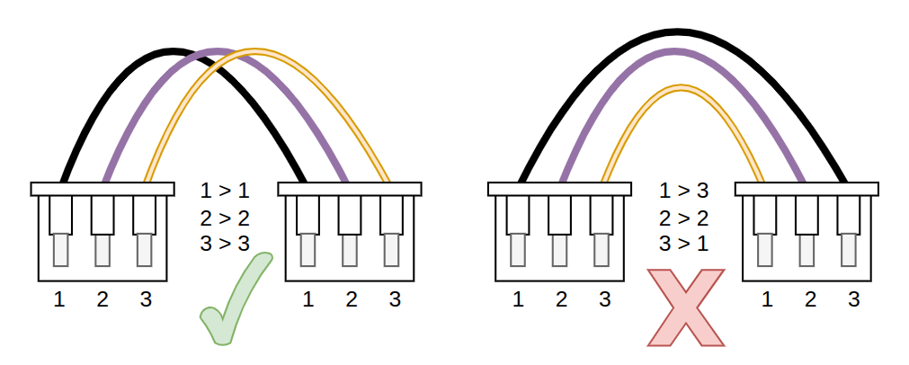
Termination
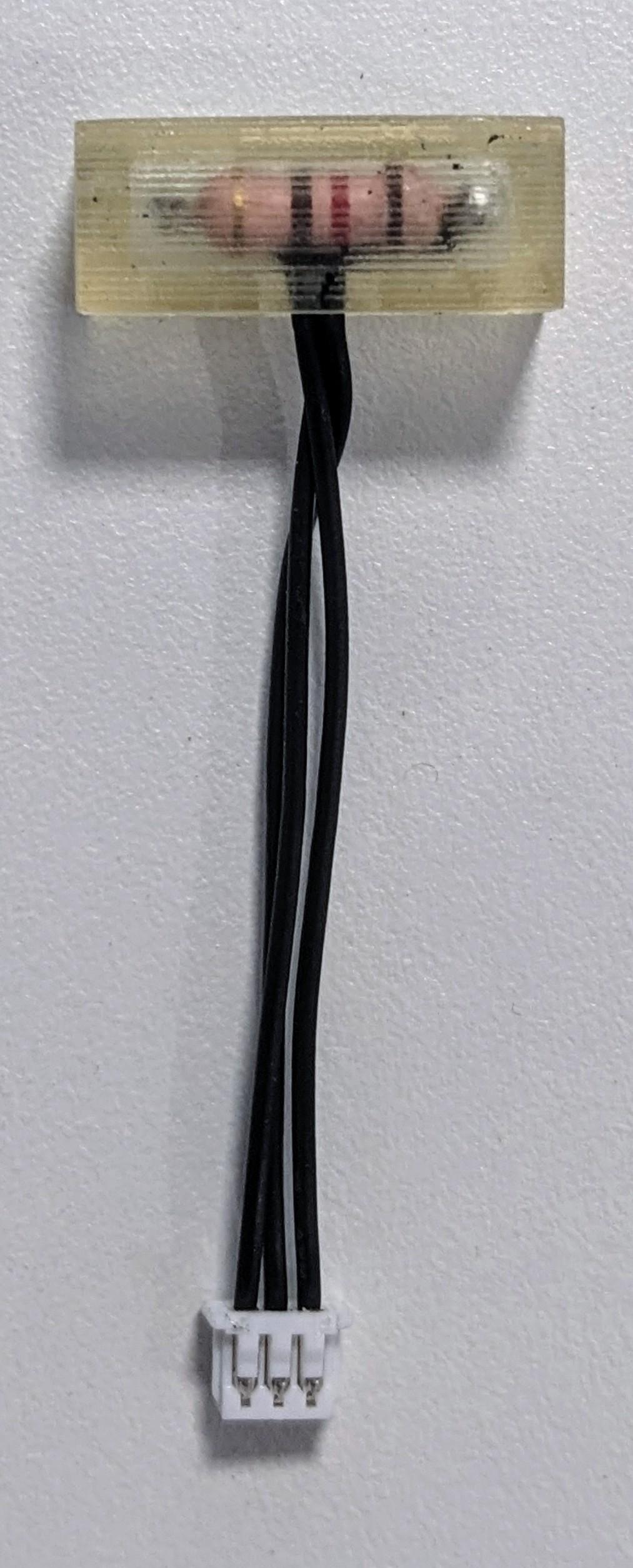
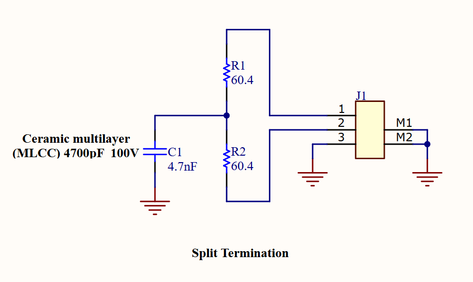
Place one CAN-Terminator at each physical end of the CAN bus. These TRs are not usually available on the market. They can either be made by the user or provided by PULSAR HRI.
CAN-Terminator assemblies use a 3-pin Molex PicoBlade connector with components between CAN-H and CAN-L. A minimal version uses a 120 Ω resistor:
A noise-rejecting version can also include capacitors:
Continue with CAN FD connectivity.